CAN
The CAN (Controller Area Network) bus is a serial, two-wire, multi-master communication bus originally developed by Bosch for use in the automotive industry. Its technical specification is defined in the ISO 11898 standard, which describes both the physical and data link layers of communication.The bus is designed for reliable and deterministic transmission of short data frames, with high resistance to electromagnetic interference (EMI). This makes it well-suited for applications that require real-time information exchange.
Although CAN was initially intended for vehicles—facilitating communication between control units (e.g., ECU, ABS, airbag)—its characteristics have proven beneficial in other fields as well, including industrial automation, medical equipment, railway and maritime systems, and embedded systems.
Typical data transmitted over CAN include engine speed, pedal position, coolant temperature, or sensor status.Unlike the RS-485 bus, which only defines the physical transmission medium, CAN implements a complete data link layer, including collision detection, bus arbitration, frame identification, and error management.
Physical layer of the CAN Bus
The physical layer of the CAN bus is described by standards ISO 11898-2, ISO 11898-3, SAE J2411, and ISO 11992. Similar to RS-485, CAN utilizes differential signaling, a bus topology, and devices interconnected via twisted-pair wiring. The total length of the bus depends on the data transmission rate.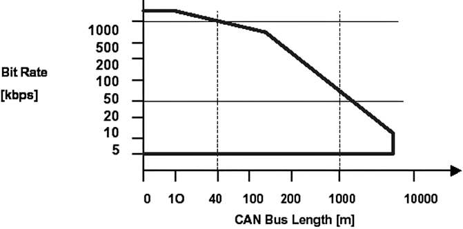
The maximum bus length is 6 km at a transmission speed of 10 kbit/s. According to the ISO 11898 standard, the required voltage range on the bus is from −2 V to +7 V. The ends of the bus must be properly impedance-matched, typically using termination resistors with a value of 120 Ω.
Data link layer of the CAN Bus
The data link layer protocol, as defined by the ISO 11898-1 standard, specifies how data is transmitted over the CAN bus. Messages carry either an 11-bit (standard format) or a 29-bit (extended format) identifier, which determines their priority on the network. Devices receive messages based on these identifiers—the lower the identifier value, the higher the priority of the message. A single CAN network can support the coexistence of both identifier formats. The device transmits data when the bus is idle. In the event of a collision, the device with the highest-priority identifier wins. CAN is designed for environments with high levels of interference and incorporates five error detection methods that reliably identify global faults.
| Error Type | Description |
| Bit error | The transmitting node monitors the state of the bus. Detection of a mismatch indicates a bit error, with the following exceptions:
|
| Synchronization error | Detection of six consecutive identical bits in the part of the frame where bit stuffing is used |
| CRC error | A mismatch between the CRC value calculated by the receiver and the received CRC value |
| Form error | Incorrect value of fixed-format bits (e.g., RTR, IDE) |
| Acknowledgment error | During the ACK interval, no dominant value appears on the bus |
Bus arbitration in CAN
It is a process that determines which device on the bus is allowed to transmit when multiple devices attempt to transmit simultaneously. Bus arbitration is handled using inverted logic.
Logic levels on the CAN bus:
- High (logical 1) - recessive state
- Low (logical 0) - dominant state
Access to the bus is random. When two or more devices attempt to transmit on the bus simultaneously, a non-destructive arbitration occurs. In this method, the message with the higher-priority identifier is transmitted, while the message from the lower-priority device is suspended. The dominant bit (logical 0) always overrides the recessive bit (logical 1). This causes the message with the lowest binary value of the identifier to remain on the bus.
Application Layer of the CAN Bus
As mentioned earlier, CAN defines the bottom two layers of the ISO-OSI model. Therefore, for different applications, various communication protocols for the application layer have been developed:
CANopen:
- A protocol designed for use in devices where precise positioning is required
- The standard is defined by EN 50325-4
- The CANopen specifications are managed by the CiA (CAN in Automation) organization
DeviceNet:
- Intended for use in industrial automation
- The standard is defined by EN 50325-2
- The DeviceNet specifications are managed by ODVA (Open DeviceNet Vendor Association)
SDS:
- A protocol developed by Honeywell, intended for automation systems
- Standardized under EN 50325-3
SAE J1939:
- Corresponds to ISO 11992 / ISO 11783
- A protocol covering both the physical and application layers, used in road vehicles (ISO 11992) and agricultural and forestry machinery (ISO 11783)