RS 485
A standard industrial, two-wire communication bus for serial communication between multiple devices. It allows long-distance transmissiom up to 1.2 km without the need for repeaters and is suitable for use in noisy environments. This bus supports communication between a maximum of 32 devices. When the bus is in an idle state, all devices connected to it must be in a high-impedance state, which ensures proper bus operation. Only one device may transmit at any given time. Bus communication control and arbitration are left to higher protocol layers, as RS-485 defines only the physical layer. The bus uses differential data signaling.
Connection of devices to the RS-485 bus
RS-485 uses a bus topology, meaning that devices are connected in parallel. A twisted pair of wires is used to interconnect the devices, which helps to eliminate interference, especially of inductive nature. Full-duplex communication requires a four-wire bus, allowing data to be sent and received simultaneously. However, most applications use half-duplex communication, where data is transmitted in one direction at a time.Industrial RS-485 cables are of the sheathed, unshielded, twisted-pair type, (UTP), with a characteristic impedance of 120 W and 22–24 AWG.
Voltage levels on the bus
RS-485 standard conform drivers provide a differential output of a minimum 1.5 V across a 54-Ω load, whereas standard conform receivers detect a differential input down to 200 mV. The two values provide sufficient margin for a reliable data transmission even under severe signal degradation across the cable and connectors. This robustness is the main reason why RS-485 is well suited for long-distance networking in noisy environment.
Bus Termination and Stub Length
Termination of the bus with resistors (terminators) and keeping the stubs from the main line as short as possible are crucial for ensuring proper data transmission, especially in networks with high data rates or long distances. Without proper termination, signal reflections can occur, which degrade signal integrity. Proper bus termination requires impedance matching of the terminators to the characteristic impedance of the bus line. The standard resistance value for RS-485 terminators is 120 Ω.
Applications in noisy environments often have the 120-Ω resistors replaced by two 60-Ω, low-pass filters to provide additional common-mode noise filtering. It is important to match the resistor values, (preferably with 1% precision resistors), to ensure equal rolloff frequencies of both filters. Larger resistor tolerances, (i.e., 20%), cause the filter corner frequencies to differ and common-mode noise to be converted into differential noise, thus compromising the receiver’s noise immunity.
The electrical length of a stub, (the distance between a transceiver and cable trunk), should be shorter than 1/10 of the driver’s output rise time, and is given through:
𝐿 ≤ (𝑡𝑟/10)·(𝑣/𝑐)
Where:
L = maximum stub lenght [m]
tr= driver [10/90] rise time [ns]
v = signal velocity of the cable [m/s]
c = speed of light [m/s]
Failsafe
Failsafe operation is a receiver’s ability to assume a determined output state in the absence of an input signal.
Three possible causes can lead to the loss of signal (LOS):
- Open-circuit, caused by a wire break or by the disconnection of a transceiver from the bus
- Short-circuit, caused by an insulation fault connecting the wires of a differential pair to another
- Idle-bus, occurring when none of the bus drivers is active
Because these conditions can cause conventional receivers to assume random output states when the input signal is zero, modern transceiver designs include biasing circuits for open-circuit, short-circuit, and idle-bus failsafe, that force the receiver output to a determined state, under an LOS condition. A drawback of these failsafe designs is their worst-case noise margin of 10 mV only, thus requiring external failsafe circuitry to increase noise margin for applications in noisy environments.
Data rate versus bus length
The maximum bus length is limited by the transmission line losses and the signal jitter at a given data rate. Because data reliability sharply decreases for a jitter of 10% or more of the baud period.In the picture below, we can see the characteristic of cable length versus data rate for a conventional RS-485 cable at 10% signal jitter.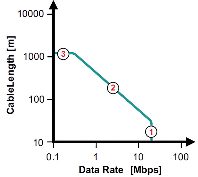
Communication protocols suitable for RS-485
- Modbus RTU - simple to implement and widely supported
- Profibus DP - designed for industrial enviroments, offering right robustness and speed
- BACnet MS/TP - used in building automation, suitable for HVAC integration
- DMX-512 - used for controlling lighting technology